Our engineering manager John Meijer shares his knowledge. Every month, he discusses a different topic in the field of electrical safety. This time his blog is about how to determine the emergency stop circuit.
How do you determine the safety category of the emergency stop?
How do you determine whether an emergency stop circuit is needed? And how do you then determine which safety level and which stop category it must meet?
Our customers often ask us to design a cabinet with an emergency stop relay. The first question we then ask is which level of safety and which stop category the emergency stop must meet. We will regularly receive an answer such as: ‘just make sure it complies with the European Machinery Directive’. This shows that many people do not (properly) know what the procedure is to determine what level of safety should be applied before the emergency stop. Therefore, I will try to explain what steps you need to go through to determine the right category.
The emergency out or emergency stop is necessary in Europe under the machine directive (2006/42/EC) and the standards harmonized according to this directive: NEN-EN-ISO12100, NEN-EN-IEC 60204-1 and NEN-EN-ISO13850.
Before we go through the steps to arrive at the correct emergency stop circuit, it is good to know what the various standards mean by ‘risk’ and ‘damage’.
Physical injury or health damage
NEN-EN-ISO 12100 provides you, the designer, with valuable information about the fundamental concepts and principles for the safe design of machines to prevent damage. The definition of ‘damage’ in this standard refers in particular to physical injury or damage to health. The very first step you need to take, before you start designing a control box, is to determine the risks of the machine or installation. So ask yourself whether the machine or installation is designed and built in such a way that it can be operated, adjusted and maintained, without exposing anyone to risks when performing actions under the established conditions.
Damage to the environment, nature, buildings, machines and surroundings
The term ‘damage’ is more broadly defined than ‘physical injury’ or ‘damage to health’. It is therefore necessary to also take other harmful effects into account during a risk assessment. Think of damage to the environment, expensive process installations, machines, buildings or surroundings.
HAZOP method
With regard to process safety, you must take into account ATEX 153 for explosion safety, Explosion safety document, Risk assessment for installation, QRA processes (Quantitative Risk Assessment) and HAZOP processes. During the design phase of process installations, the HAZOP method (Hazard and Operability study) is usually applied. The HAZOP method is very suitable for the evaluation of process-related risks. The method includes a structured and systematic way of identifying and safeguarding potential risks in all parts of the process. It is the essential basis for process safety and is laid down in an international standard (NEN-EN-IEC 61882). The step-by-step plan below is therefore based on the HAZOP method.
Take a step-by-step approach
Perform the following steps to determine the emergency stop circuit:
- Step 1: Make an inventory of the risks of the machine or installation.
- Step 2: Make an inventory of the common life phases of the machines or installation components.
- Step 3: Make a risk assessment.
- Step 4: Design or choose the right SIL / PL solutions to reduce risks.
- Step 5: Repeat the risk assessment.
Step 1: Make an inventory of the risks of the machine or installation
Start by using your common sense and identify which possible dangers are immediately visible. First try to solve these mechanically, for example by placing protective covers on rotating or moving parts, hot surfaces, etc.
In addition, make use of a checklist in which almost all hazards are mentioned during the risk analysis. For example, with machine safety, you must take into account the CE marking, Work Equipment Directive, Electrical Safety, Safety-related Controls SIL / PL and the Pressure Equipment Directive.
Step 2: Make an inventory of the common life phases of the machines or installation components
This step of the risk assessment is all about the life stages of a machine. Make an inventory of the common life phases of similar machines within the industry. A machine has the following life stages:
- transport;
- assembly, installation and commissioning;
- adjustment, setting / programming and / or process change;
- being in operation;
- cleaning and maintenance;
- detecting and rectifying defects;
- decommissioning and dismantling.
Step 3: Make a risk assessment
Then make a risk assessment, for example name:
- mechanical hazards (pinching, crushing, cutting, trimming, stabbing, impacting, etc.);
- electrical hazards (risk of contact with live parts, short circuit, etc.);
- thermal hazards (hot or cold surfaces);
- risks due to incorrect operation (unintentional starting);
- risks due to defects in the machine;
- hydraulic and pneumatic risks.
NEN-EN-ISO 12100 explains how to make a full risk assessment. In this standard you will find a number of useful tables that will help you to facilitate this process.
The risk assessment may reveal a number of hazards that cannot be resolved mechanically. For this, safety circuits must be devised. This can be done by placing a sensor on a fence, which switches off the moving parts when the gate is opened. You can also place a sensor on an inspection hatch, which switches off the machine when opened, or install two-handed controls, and so on. The local manual emergency stops must also comply with a certain safety category. You determine which safety category that is on the basis of the weighting factor in the risk graph. You need the result of the risk graph again in step 4.
Risk graph
NEN-EN-ISO 13849-1
In order to determine the required PL, you have to take into account several criteria: the extent of the damage, the frequency and duration of stay, as well as options for preventing the hazard. Use the table below to determine the correct PL.
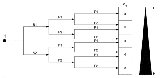
Parameters risk graph
S: severity of the injury
- S1 – minor injury (usually reversible)
- S2 – serious injury, up to and including death (usually irreversible)
F: frequency and / or duration of exposure to hazard
- F1 – rarely to more often and / or of short duration
- F2 – often to continuous and / or of long duration
P: possibility of avoiding the danger
- P1 – possible under certain circumstances
- P2 – hardly possible
Step 4: Design or choose the right SIL / PL solutions to reduce risks
NEN-EN-IEC 62061 (SIL) describes the functional safety aspects of electrical, electronic and programmable control systems. NEN-EN-ISO 13849-1 (PL) describes the implementation of the safety-related parts of control systems. The specification of the functional requirement is about describing the respective safety functions. To ensure this, you need to capture the critical interfaces with other control functions and error responses. In addition, you must determine the Safety Integrity Level (SIL) or the Performance Level (PL). Nowadays there are also safety PLCs on the market that you can use for your emergency stop circuits. However, tested, certified software blocks must be used, the functionality of which you cannot adjust yourself in order to prevent errors or failures.
The fact that all components individually have a specific SIL classification does not necessarily mean that the entire circuit automatically complies with that SIL class. First the probability of failure must be calculated with all components of the safety circuit. Only then you can determine which SIL classification the circuit has.
Stop categories
There are several stop categories. Sometimes it can be dangerous to suddenly switch off the power supply to a machine or installation completely. In that case you have to switch off the machine in steps. It is important to include this in the design.
In the previous version of the NEN-EN-IEC 60204-1 standard, three ‘stop categories’ were already defined:
- Stop category 0: stopping movements by immediately switching off the power supply;
- Stop category 1: controlled stop (cruising, braking, etc.) and then disconnect the power supply;
- Stop category 2: controlled stopping where the energy may remain available.
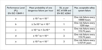
Safety category
On the basis of the performance level that comes out of the risk graph (see step 3), you determine the design for the safety category of the emergency stop. Use the table below.
The NEN-EN-IEC 60204-1 states, among other things:
Emergency shutdown is achieved by electromechanical switchgear interrupting the relevant power supply to the machine. This activates a stop function of stop category 0 of machine drives connected to this incoming power supply. If the stop function in category 0 is not possible on a machine, other measures may be necessary. Then think of basic protection, so that emergency shutdown is not necessary. The color red must be used for emergency stop switches and emergency shutdown devices. Emergency stop devices must be easily accessible and must be located at any place where the activation of an emergency stop may be required. An emergency stop must always be hardware-based and must not be via a logic module or PLC (with the exception of a safety PLC).
Examples
How do you perform the switching of different performance levels within stop category 0? I will explain this below based on a number of examples.
Safety category 1
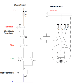
Safety category 1
Single channel emergency stop circuit with controls. This control detects cable breaks and earth leaks in the control circuit.
Safety category 2
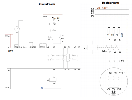
Safety category 2
Single channel emergency stop circuit with controls. This control detects cable breaks and earth leaks in the control circuit.
Safety category 3
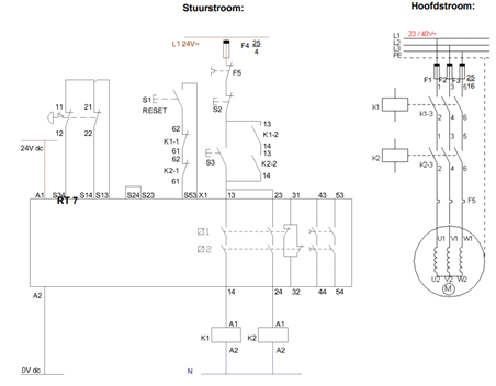
Safety category 3
Dual-channel emergency stop circuit with controls. This control detects cable breaks and earth leaks in the control circuit. Cross-connections between the control circuits are not recognized. The safety function is guaranteed in case of a single fault. Some, but not all, errors are detected. An accumulation of undetected errors can lead to the loss of the safety function.
Safety category 4
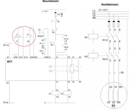
Safety category 4
Dual-channel emergency stop circuit with controls. This control detects cable breaks and earth leaks in the control circuits. Cross-connections between the control circuits are also recognized. The safety function is guaranteed at all times. Errors must be detected in time so that no loss of the safety function occurs.
Pay attention!
Do not forget to ground the zero of the safety circuit, otherwise you will have a floating circuit and an earth fault will not be detected; with all the associated risks.
Step 5: Repeat the risk assessment
The check is the last step of the risk assessment: are the risks sufficiently reduced with the correct measures. Chapter 6 of the NEN-EN-ISO 12100 standard provides a general approach for reducing risks. This is partly a technical implementation of the essential health and safety requirements of Annex I of the Machinery Directive. Chapter 6 provides the basic provisions for a safe machine. This ranges from fixed guards and two-hand operation to the user manual. The entire range of protective measures is discussed here. Where matters need more explanation, there is a reference to a specific standard on that subject. NEN-EN-ISO 12100 is the basis for the design. When you apply this standard, you automatically go through the process that the machinery directive prescribes for the designer. If more information is required, you can use more specific standards.
When high operational reliability is required, all components (sensors), safety relays and actuators must be included in the SIL calculation. This requires some specialism. Do you have little or no experience with this yourself? Then it is advisable to call in an expert agency. They will then, together with the designer of the machine or installation, make a good and thorough risk analysis that meets all the requirements of the machinery directive. Ultimately, the analysis is used to certify the installation or machine CE.
Tip from me to you
First and foremost: there are agencies that take care of the risk assessment. There is a lot involved if you want to carry out the assessment yourself. Are you going to get started yourself? Then take the “Praktijkgids Risicobeoordeling in het kader van Machinerichtlijn”. This guide was written by Ir. Paul Hoogerkamp (member of various standards committees) and published by NEN. Unfortunately the guide is only available in Dutch, but it provides guidance on how to make a thorough risk assessment and thus include the correct emergency stop circuit in your design.