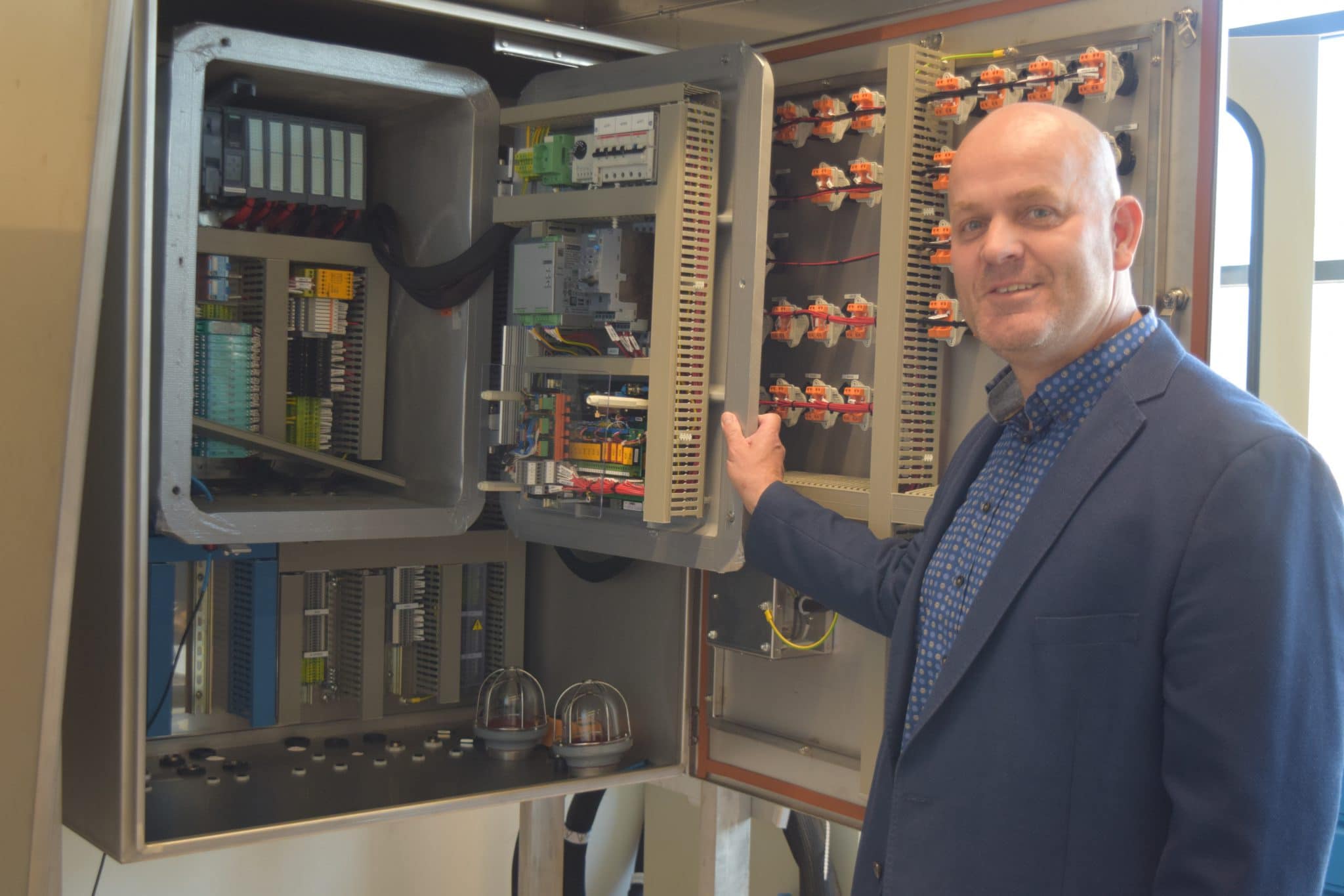
 Our engineering manager John Meijer shares his knowledge. Every month, he discusses a different topic in the field of electrical safety. This time his blog is about Ex i circuits.
Why Ex i circuits?
It often happens that we receive design packages for control cabinets that do not comply with current laws and regulations. According to the ATEX 153 directive, you must prevent the risk of explosion by taking certain measures. That is why I would like to mention a few points of interest that are important in the design of intrinsically safe circuits such as: building an Ex I circuit, the distance between Ex i and “dirty” circuits, grounding and documentation of Ex i circuits.
What is Intrinsic safety
Intrinsic safety is achieved because a circuit contains so little energy that it cannot cause ignition. A circuit can be made intrinsically safe by limiting four components: amperage, voltage, power, and temperature. This form of protection can only be applied to circuits that operate at relatively low power.
Building an intrinsically safe power chain
An intrinsically safe circuit is not about a single device, but about the entire circuit. A circuit in which (even in the event of damage, short-circuits or other specific conditions) no sparks or thermal effects can occur that could ignite an explosive atmosphere. This function must also be maintained in the event of a fault in one of the components in the circuit.
Construction of an intrinsically safe circuit
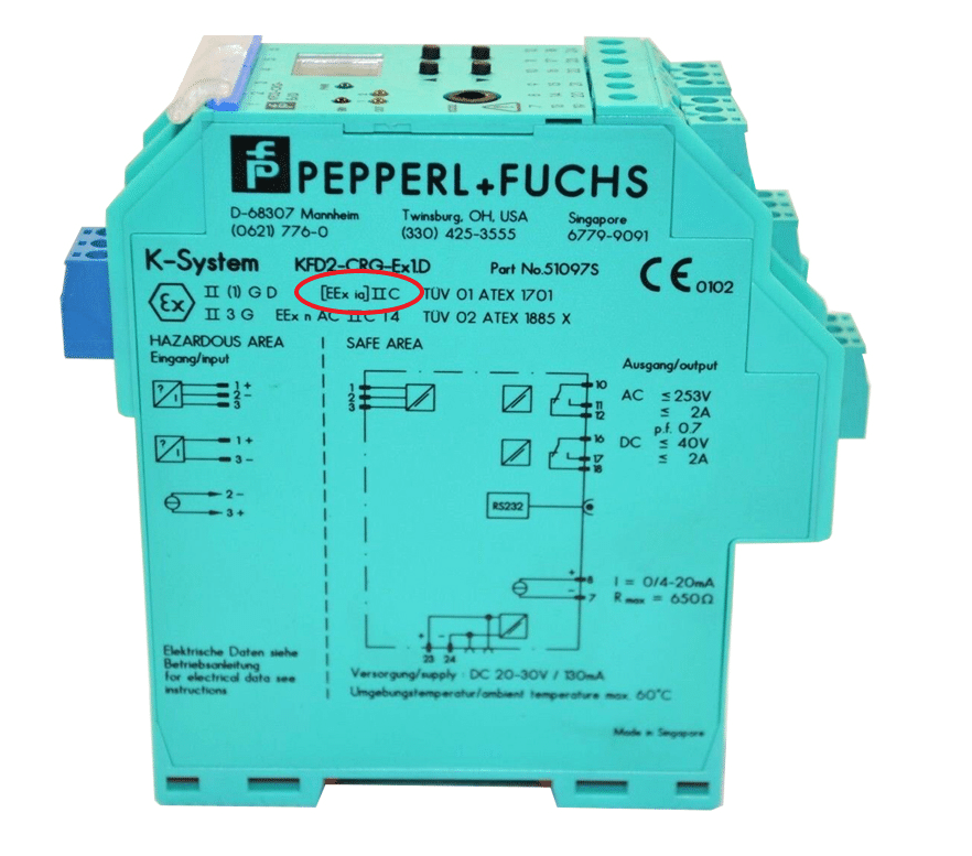
Photo 1: marking on corresponding device
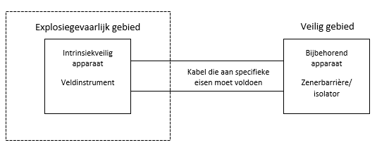
An intrinsically safe circuit contains at least the following three components:
- An intrinsically safe device (field instrument) in the hazardous area;
- A corresponding device (Zener barrier or isolator) in the safe area (or Zone 2);
- A connecting cable between the hazardous and the safe area.
The corresponding device limits the amount of energy that goes to the circuit in the hazardous area. You will find the marking of the corresponding device on the device itself between the brackets (see photo 1, circled in red). The protection method can be found on the device between the parentheses. The marking on the corresponding device (Zener barrier or isolator) is not intended for this device itself, but for the field instrument (intrinsically safe device) that you connect to it.
What does the standard say about intrinsic safety?
In chapter 16 of the NEN-EN-IEC 60079-14 standard for explosive atmospheres (part 14: electrical installations design, selection and erection), a number of things are mentioned that you should consider in your design. A few important topics are the distances between the blue and gray wire ducts and connection terminals within control panels.
Distance between blue and gray wire ducts
We often see that the distance of 50mm between the blue (clean) and gray (dirty) wire ducts and terminals, is not maintained in junction boxes with non-intrinsically safe and intrinsically safe power chains. In practice there is regular discussion whether or not this is mandatory or permitted. So let’s see what part 14 of the standard says about this.
Installations with intrinsically safe circuits must be placed in such a way that their intrinsic safety is not adversely affected by external electric or magnetic fields. Consider, for example, nearby electrical cables or single-core high-voltage cables. This can be achieved by using shields and / or twisted pair wires, or by maintaining an appropriate distance from the source of the electric or magnetic field. It is also said that the airway between insulated conductive parts of intrinsically safe circuits and non-intrinsically safe circuits should be at least 50mm.
So in summary: blue and gray wire ducts may not be mounted on the mounting plate without spacing, against or next to each other, unless you place a metal partition plate where the airway between the dirty and clean part is at least 50mm. The metal partition between the wire ducts must therefore protrude 25mm above the wire ducts.
Distance between blue and gray terminals
You must install all cables in such a way that you can ensure that they cannot inadvertently be connected in intrinsically safe circuits to cables in circuits that are not intrinsically safe. If a wire comes loose, it cannot inadvertently touch a non-intrinsically safe terminal. That is why the minimum distance of 50mm between the blue (clean) and the other (dirty) terminals also applies here. You may also choose other means of separation, in accordance with NEN-EN-IEC 60079-11 (part 11: equipment protection by intrinsic safety “I”). The intrinsically safe terminals must be separated by at least 3mm from any earthed parts, such as the metal side of an enclosure, etc.
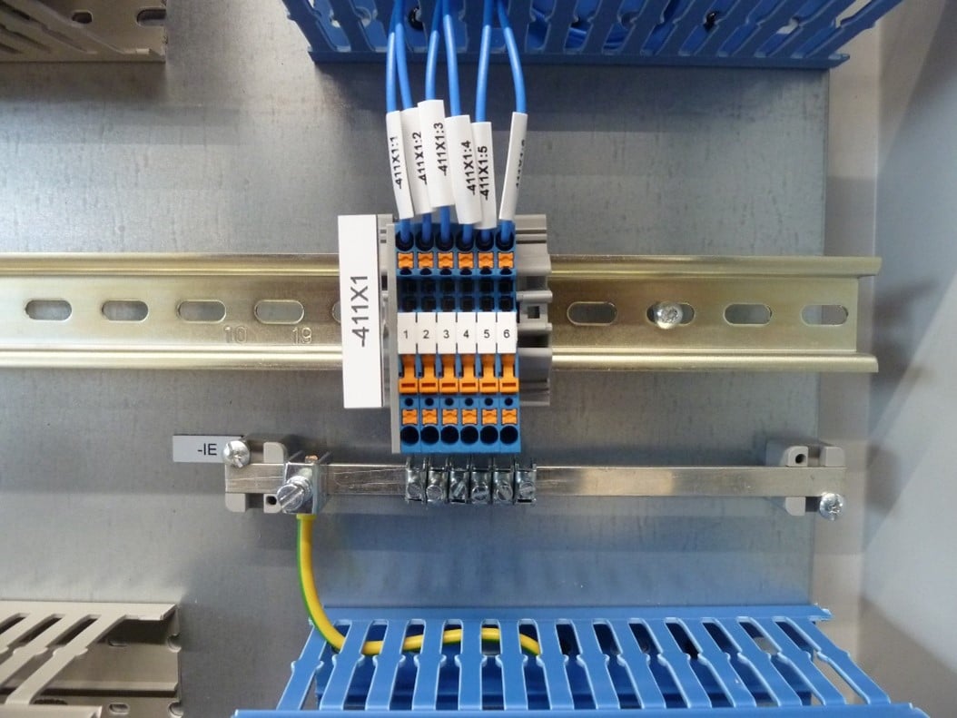
Photo 2: isolated ground rail for the Ex i signals
Grounding Zener barriers
In intrinsically safe circuits, the earthing terminals of safety barriers, without galvanic isolation (e.g. Zener barriers), must be connected to the equipotential bonding line by the shortest possible route. Alternatively, these earthing terminals must be reliably connected to a system earth so that the impedance (from connection point to system earth of the central power system) is less than 1 Ω. You may do this by connecting to the busbar or by using separate earthing points. The conductor used must be insulated to prevent fault currents to earth. Care should also be taken to ensure that mechanical protection is in place where there is a high risk of damage. The core cross-section of the earth connection must be formed by at least two separate conductors, each with an assigned value to carry the highest possible current that can flow continuously, each with a minimum of 1.5mm2 (copper) or at least one conductor of at least 4mm2 (copper).
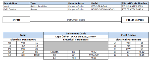
Document Ex i loop
A document must be created in which you describe all intrinsically safe systems. This document should describe an analysis of the security level. This means that you have to make a calculation in which you check the capacitance, resistance and current of all components in the loop. This is to find out whether the energy present in the loop remains below the limit at which an explosion can occur. The entire loop must also be drawn in a sketch, with all components and parameters being named. See an example of our document below.
Requirements Ex i cables
You may not just use any blue cable with Ex i circuits. You may only use cables with a nominal insulation value of at least 500VAC or 700VDC, between conductor and earth, conductor and screen and between screen and earth. The diameter of individual conductors, or strands of multi-strand conductors, within the hazardous area must not be less than 0.1mm. For multi-core cables, the following applies: 500VAC or 700VDC between interconnected individual wires and the screen or 1000VAC or 1400VDC between a bundle, consisting of half of all interconnected individual wires in relation to the other half. The insulation value must be tested and demonstrated with a document from the cable supplier, the manufacturer or the installer.
Pay attention!
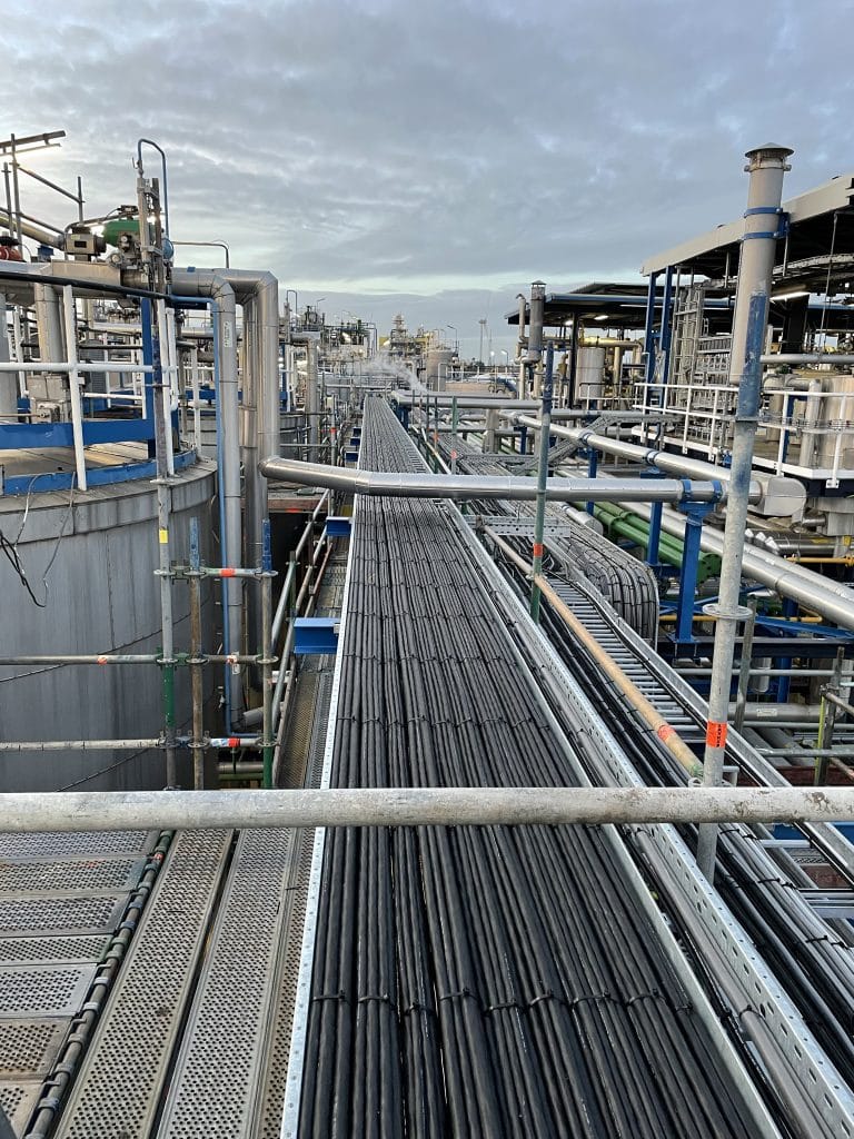
Only intrinsic circuits may be incorporated within an intrinsically safe cable! Intrinsically safe cables and non-intrinsically safe cables may only be installed in the same cable tray or conduit if all cabling is provided with metal shielding!
Unused wires
Unused conductors in multi-core cables must be well insulated on the field side from earth and from each other by terminating them at the ends. On the clean side in the cabinet, these wires must be connected to the insulated clean earth of the corresponding device. This should preferably have a different color: they are often marked yellow / black. The wires must be well insulated in the field from the dirty earth and from each other by means of suitable insulated terminals at the other end. The use of heat shrink tubing or termination of the unused conductor in suitable terminals is permitted. So the spare wires must not come into contact with the “dirty earth” anywhere, but only with the clean earth to which the corresponding device (e.g. the Zener barrier) is connected.
Marking cables
Cables containing intrinsically safe circuits must be marked. The color used for marking on cable sheaths or coverings must be light blue. Where intrinsically safe circuits are marked with a light blue cable, this color cable should not be used for other purposes. If you do this, it can cause confusion or impair the effectiveness of the marking of intrinsically safe power chains.
Armored cable
If all cables of intrinsically safe circuits, or all cables of circuits that are not intrinsically safe, are armored or provided with a metal sheath or screen, then intrinsically safe cables need not be marked.
Requirements for wiring diameter
The diameter of the individual wires, or strands of twisted conductors within the hazardous area, must be at least 0.1mm. If more than one Ex i circuit goes through the same cable, the core diameter must be at least 0.2mm. Ex i cables must be marked, so that it is clear that they are part of an Ex i circuit.
Below are a number of practical examples (photo 3) where no 50mm2 airway is used, by creating a distance between the wire ducts or placing a metal separation plate between them. The standard says that you must also take into account the influences of magnetic fields, such as those from nearby electrical lines or single-core high-current lines.
The photos below are a good example where you can see that the power lines from the main switch in the gray gutter run right along the blue intrinsically safe gutter, without separation or spacing of 50mm. This is not allowed.
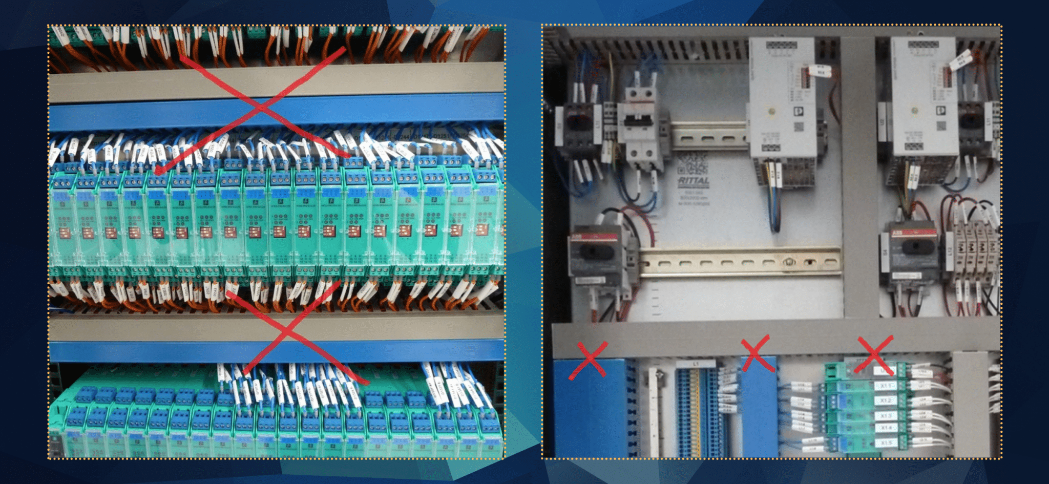
Foto 3: praktijkvoorbeelden
Questions or comments?
Do you have any questions or comments about this blog? Or do you have suggestions for a topic for the next one? Don’t hesitate to contact us, leave a message below!

Hello
I have a question about your photos. Where in standards 60079/14 does it say you cannot install an IS and non IS conduits/panel ducts side by side with out a50mm air gap?
My understanding is you cannot have less than 50mm between exposed copper conductors of IS and non IS circuits.
Thank you
Michael
Dear Michael,
Non-intrinsic conductors may not electrically affect intrinsically safe conductors. Conductors must not influence each other electromechanically. That is why you must maintain an airway of at least 50mm or place a metal partition in between that protrudes 25mm above the wiring duct. You can find this in the ATEX standard. See below what the standard says about it.
NEN-EN-IEC 60079-14 3.5.2
associated apparatus electrical apparatus which contains both intrinsically safe circuits and non-intrinsically safe circuits and is constructed so that the non-intrinsically safe circuits cannot adversely affect the intrinsically safe circuits
NEN-EN-IEC 60079-14 16.2.2.5.1
General Installations with intrinsically safe circuits shall be erected in such a way that their intrinsic safety is not adversely affected by external electric or magnetic fields such as from nearby power lines or heavy current-carrying single core cables. This can be achieved, for example, by the use of screens and/or twisted cores or by maintaining an adequate distance from the source of the electric or magnetic field.
NEN-EN-IEC 60079-14 16.4
Terminals shall be separated by a distance of at least 50 mm from non intrinsically safe terminals or connections or provided with other means of separation in accordance with IEC 60079-11.
NEN-EN-IEC 60079-14 16.5.4
The clearance distance between bare conducting parts of intrinsically safe circuits and non-intrinsically safe circuits shall be at least 50 mm or as defined in IEC 60079-11.
I hope this answered your question.
can you please also explain the scenario when the circuit is powered from hazardous area( active signals)? . Do we have to install the barriers as close to the voltage source( the field instrument in this case) as voltage is generated here?
A barrier or isolator ensures that the voltage and current are so low that no spark can occur in the explosion hazard area. The barrier or isolator must be installed in the explosion-proof area. If it concerns an intrinsically safe circuit, it is not allowed to place the barrier or isolator in the hazardous area unless you mount it in a certified Ex d housing. The barrier or isolator does not necessarily have to be close to the instrument. You should always make a loop calculation to see if too much energy is stored in your loop. Your cable acts like a capacitor and you have to include the type and length of your cable in this calculation. In general, these cables can be quite long.
Is the instrument really intrinsically safe or is it made in Ex d with a normal active analog signal? Otherwise you do not need an isolator or barrier if it is suitable for use in the specified zoning of the hazardous area.
Does the rule of 50mm separation apply to 24VDC circuits in a control panel with instrinsically safe circuits also.
Marty,
Yes also for 24VDC circuits.
The standard NEN-EN-IEC 60079-14 states that the airway between insulated conductive parts of intrinsically safe circuits and all other non-intrinsically safe circuits must be at least 50 mm.
Intrinsically safe circuits must be placed in such a way that their intrinsic safety is not adversely affected by external electric or magnetic fields.
Hi John,
Re cable glands, Intrinsically safe cabling from within an Atex zone returning to a control cabinet outside of Atex zone, do these cables need to pass thru Atex certified glands (Blue), or will “Standard” glands that are segregated from non IS I/O and AC power glands and indicated as “IS circuits only” or similar be acceptable? – Thanks.
Hi Stuart,
The advice is to apply blue cable glands so that it is clear to everyone that it concerns IS signals, but in the standard you do not read that it is mandatory.
Hi John,
The photo 2 shows isolated ground bar for Ex signals. Where do you route the other end? If it goes straight to the main PE bar then isn’t the 50mm open air gap disrupted if the PE bar isn’t right next to clean area. Or is it okay as long as the used wire is big enough and isolated the whole length from Ex ground bar to PE main ground?
This blog text has been really interesting and helpful, thanks!
Hi Ardem,
You have to connect it to the shortest practicable route tot the PE bar or to a clean earth connection of a TN-S system.
The stardard EN 60099-14 16.2.3 says:
In intrinsically safe circuits, the earthing terminals of safety barriers without galvanic isolation (for example Zener barriers) shall be:
1) connected to the equipotential bonding system by the shortest practicable route, or
2) for TN-S systems only, connected to a high-integrity earth point in such a way as to ensure that the impedance from the point of connection to the main power system earth point is less than 1 Ω. This may be achieved by connection to a switch-room earth bar or by the use of separate earth rods.
The conductor used shall be insulated to prevent invasion of the earth by fault currents which might flow in metallic parts with which the conductor could come into contact (for example control panel frames). Mechanical protection shall also be provided in places where the risk of damage is high.
Hi John,
I have a question regarding of the cable separation between IS cables and NIS cables. Is there a must of separation through the metallic tray the cables if you armored of the cables (IS and NIS)? Reading your post I got into the conclusion that you don’t need to mark the cables in blue if you armored the cable.
Best regards
The standard NEN-EN-IEC 60079-14:2014 says:
Installations with intrinsically safe circuits shall be erected in such a way that their intrinsic safety is not adversely affected by external electric or magnetic fields such as from nearby power lines or heavy current-carrying single core cables. This can be achieved, for example, by the use of screens and/or twisted cores or by maintaining an adequate distance from the source of the electric or magnetic field.
In addition to the cable requirements of 9.3.7, cables in both hazardous and non-hazardous areas shall be installed so as to ensure that intrinsically safe circuit cables cannot be inadvertently connected to circuit cables which are not intrinsically safe. This may be achieved by using cables which are armoured, metal sheathed or screened for at least one type of circuit (e.g. all circuits which are not intrinsically safe are run in armoured cable or all intrinsically safe circuits are armoured). If all intrinsically safe circuit cables or all cables of circuits which are not intrinsically safe are armoured, metal sheathed or screened, then marking of intrinsically safe circuit cables is not required.